Kerala-IoT-Challenge
Experiment 1 - Hello World LED Blinking
A basic Program similar to printing “Hello World “ in any programming language. The Aim is to blink an LED using Arduino Uno Board.
Arduino Uno is an open-source microcontroller board developed by Arduino.cc. It has several advantages over the conventional microcontrollers. It comes with a pre-tested software and hardware libraries and has its own integrated development environment (IDE). Also it is less expensive & beginner friendly.
Components Required
- Arduino Uno Board
- USB Cable
- LED (Any Color) x 1 Nos
- 220 OHM Resistor X 1 Nos
- Breadboard
- Jumper Wires (Male to Male ) X 2 Nos
Circuit Diagram
.png?raw=true)
Code
int ledPin = 10; // define digital pin 10.
void setup()
{
pinMode(ledPin, OUTPUT);// define pin with LED connected as output.
}
void loop()
{
digitalWrite(ledPin, HIGH); // set the LED on.
delay(1000); // wait for a second.
digitalWrite(ledPin, LOW); // set the LED off.
delay(1000); // wait for a second
}
Output
The LED is blinked with a time interval of 1 second

Experiment 2 : Traffic Light
In the previous program, we have done the LED blinking experiment with one LED. Now, it’s time to up the stakes and do a bit more complicated experiment-traffic lights. Actually, these two experiments are similar. While in this traffic lights experiment, we use 3 LEDs with different colors rather than 1 LED.
Components Required
- Arduino board *1
- USB cable *1
- Red M5 LED*1
- Yellow M5 LED*1
- Green M5 LED*1
- 220Ω resistor *3
Circuit Diagram
.png?raw=true)
Code
int redled =10; // initialize digital pin 10.
int yellowled =7; // initialize digital pin 7.
int greenled =4; // initialize digital pin 4.
void setup()
{
pinMode(redled, OUTPUT);// set the pin with red LED as “output”
pinMode(yellowled, OUTPUT); // set the pin with yellow LED as “output”
pinMode(greenled, OUTPUT); // set the pin with green LED as “output”
}
void loop()
{
digitalWrite(greenled, HIGH);//// turn on green LED
delay(5000);// wait 5 seconds
digitalWrite(greenled, LOW); // turn off green LED
for(int i=0;i<3;i++)// blinks for 3 times
{
delay(500);// wait 0.5 second
digitalWrite(yellowled, HIGH);// turn on yellow LED
delay(500);// wait 0.5 second
digitalWrite(yellowled, LOW);// turn off yellow LED
}
delay(500);// wait 0.5 second
digitalWrite(redled, HIGH);// turn on red LED
delay(5000);// wait 5 seconds
digitalWrite(redled, LOW);// turn off red LED
}
Output
In Traffic light the green LED blink about 5 second, then it is turnoff. Then the yellow LED blinks 3 times with a time interval of 0.5 second.Then the red LED blink about 5 seconds. This process continues.
Experiment 3 : LED Chasing Effect
We often see billboards composed of colorful LEDs. They are constantly changing to form various light effects. In this experiment, we compile a program to simulate LED chasing effect. The long lead of LED is the positive side; short lead is negative.
Components Required
- Led *6
- Arduino board *1
- 220Ω resistor *6
- Breadboard *1
- USB cable*1
- Breadboard wire *13
Circuit Diagram
.png?raw=true)
Code
int BASE = 2 ;  // the I/O pin for the first LED
int NUM = 6;   // number of LEDs
void setup()
{
   for (int i = BASE; i < BASE + NUM; i ++)
   {
     pinMode(i, OUTPUT);   // set I/O pins as output
   }
}
void loop()
{
   for (int i = BASE; i < BASE + NUM; i ++)
   {
     digitalWrite(i, LOW);    // set I/O pins as “low”, turn off LEDs one by one.
     delay(200);        // delay
   }
   for (int i = BASE; i < BASE + NUM; i ++)
   {
     digitalWrite(i, HIGH);    // set I/O pins as “high”, turn on LEDs one by one
     delay(400);        // delay
   }
}
Output
LED with chasing effect

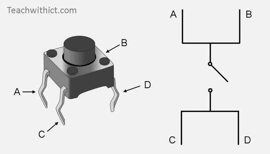
Experiment 4: Button Controlled LED
An experiment to light an LED using a Push Button.
Components Required
- Arduino Uno
- Button switch*1
- Red M5 LED*1
- 220ΩResistor*1
- 10KΩ Resistor*1
- Breadboard*1
- Breadboard Jumper Wire*6
- USB cable*1
Circuit Diagrams
.png?raw=true)
Code
int ledpin=11;// initialize pin 11
int inpin=7;// initialize pin 7
int val;// define val
void setup()
{
pinMode(ledpin,OUTPUT);// set LED pin as “output”
pinMode(inpin,INPUT);// set button pin as “input”
}
void loop()
{
val=digitalRead(inpin);// read the level value of pin 7 and assign if to val
if(val==LOW)// check if the button is pressed, if yes, turn on the LED
{ digitalWrite(ledpin,LOW);}
else
{ digitalWrite(ledpin,HIGH);}
}
Output
When the push button is pressed the LED is turned on otherwise it is off.

Experiment 5 : Buzzer
An experiment to understand the working of a buzzer.
Components Required
- Arduino Uno
- Buzzer*1
- Breadboard*1
- Breadboard Jumper Wire*2
- USB cable*1
Circuit Diagrams
.png?raw=true)
Code
int buzzer=8;// initialize digital IO pin that controls the buzzer
void setup()
{
  pinMode(buzzer,OUTPUT);// set pin mode as “output”
}
void loop()
{
digitalWrite(buzzer, HIGH); // produce sound
}
Output
The Buzzer makes beep sound.
Experiment 6 : RGB LED
An experiment to understand the working of a RGB LED.
Components Required
- Arduino Uno
- USB Cable * 1
- RGB LED * 1
- Resistor *3
- Breadboard jumper wire*5
Circuit Diagrams
.png?raw=true)
Code
int redpin = 11; //select the pin for the red LED
int bluepin =10; // select the pin for the blue LED
int greenpin =9;// select the pin for the green LED
int val;
void setup() {
  pinMode(redpin, OUTPUT);
  pinMode(bluepin, OUTPUT);
  pinMode(greenpin, OUTPUT);
  Serial.begin(9600);
}
void loop()
{
for(val=255; val>0; val--)
  {
   analogWrite(11, val);
   analogWrite(10, 255-val);
   analogWrite(9, 128-val);
   delay(1);
  }
for(val=0; val<255; val++)
  {
   analogWrite(11, val);
   analogWrite(10, 255-val);
   analogWrite(9, 128-val);
   delay(1);
  }
 Serial.println(val, DEC);
}
Output
The RGB LED blinks.
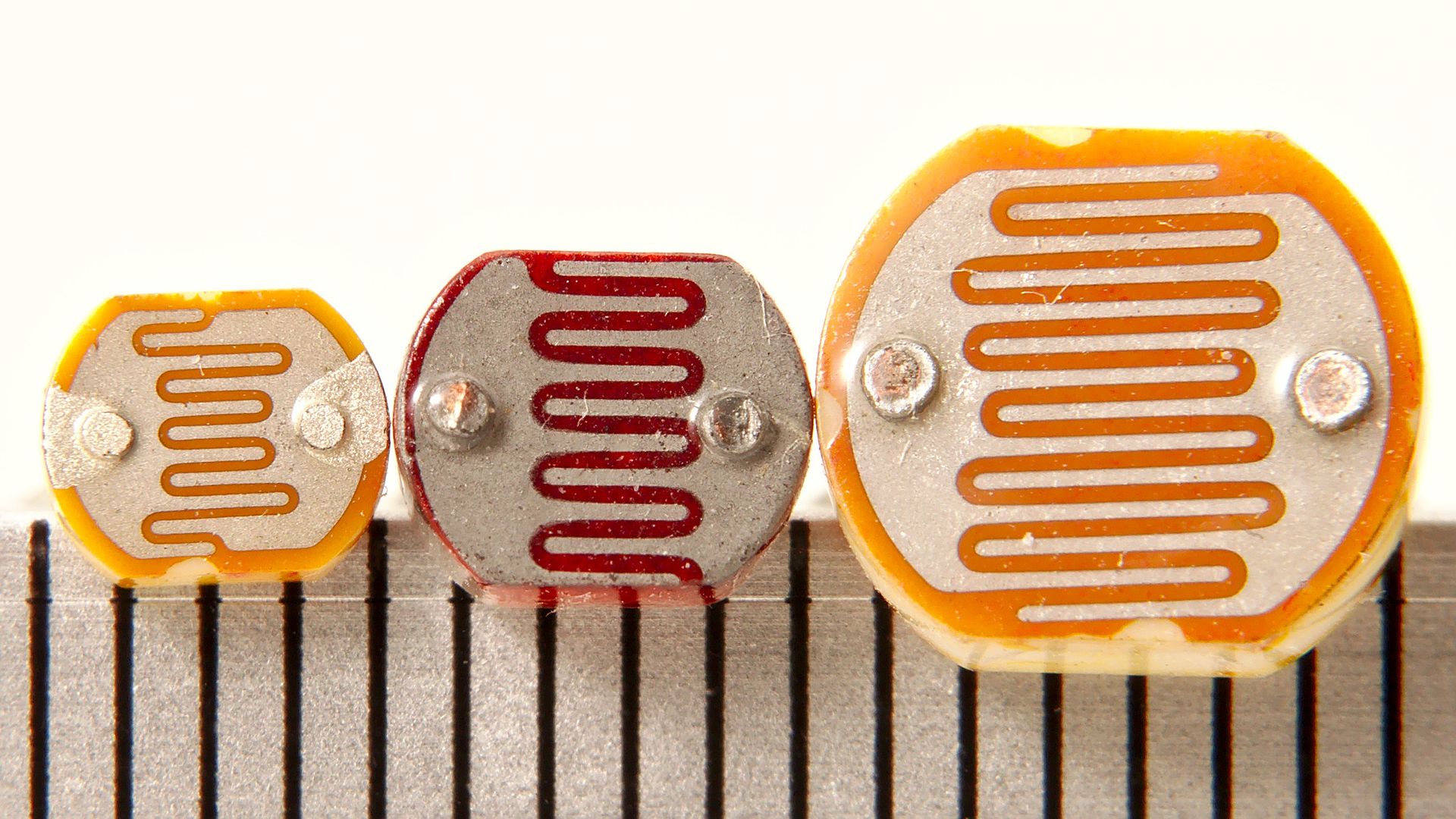
LDR : Light Dependent Sensor
Photo Resistor (Photovaristor) is a resistor whose resistance varies from different incident light strength. It’s based on the photoelectric effect of semiconductor. If the incident light is intense, its resistance reduces; if the incident light is weak, the resistance increases.
Components Required
- Arduino Uno Board
- Photo Resistor*1
- Red M5 LED*1
- 10KΩ Resistor*1
- 220Ω Resistor*1
- Breadboard*1
- Breadboard Jumper Wire*7
- USB cable*1
Circuit Diagrams
.png?raw=true)
Procedure
- Connect the 3.3v output of the Arduino to the positive rail of the breadboard.
- Connect the ground to the negative rail of the breadboard.
- Place the LDR on the breadboard.
- Attach the 10K resistor to one of the legs of the LDR.
- Connect the A0 pin of the Arduino to the same column where the LDR and resistor is connected , Then connect the other end of the 10K resistor to the negative rail.
- And then the second (free) leg of the LDR to the positive rail.
- Place the LED on the breadboard.
- Connect the 220ohm resistor to the long leg (+ve) of the LED.
- Then we will connect the other leg of the resistor to pin number 11 (digital pin) of the Arduino.
- and the shorter leg of the LED to the negative rail of the breadboard.
Code
int potpin=0;// initialize analog pin 0, connected with photovaristor (ldr)
int ledpin=11;// led pin is connected to pin 11
int val=0;// initialize variable val
void setup()
{
pinMode(ledpin,OUTPUT);// set digital pin 11 as “output”
Serial.begin(9600);// set baud rate at “9600”
}
void loop()
{
val=analogRead(potpin);// read the value of the sensor and assign it to val
Serial.println(val);// display the value of val
analogWrite(ledpin,val/70);// set up brightness(maximum value 255)
delay(10);// wait for 0.01
}
Output
When the intensity of light increased The Light Intensity of Output LED decreased. Output values are also shown in serial monitor.

Experiment 8 : Flame Sensor
An experiment to understand the working of an Flame sensor. The IR flame sensor is used to detect the presence of fire or other infrared source (Flame or a light source of a wavelength in the range of 760 nm to 1100 nm can be detected).
Components Required
- Arduino UNO
- Flame Sensor
- LED
- Buzzer
- BreadBoard
- Jumper
Circuit Diagrams
.png?raw=true)
Code
const int buzzerPin = 12;
const int flamePin = 11;
int Flame = HIGH;
int redled = 5;
int greenled = 6;
void setup()
{
  pinMode(buzzerPin, OUTPUT);
  pinMode(redled, OUTPUT);
  pinMode(greenled, OUTPUT);

  pinMode(flamePin, INPUT);
  Serial.begin(9600);
}

void loop()
{
  Flame = digitalRead(flamePin);
  if (Flame== LOW)
  {
    digitalWrite(buzzerPin, HIGH);
    digitalWrite(redled, HIGH);
    digitalWrite(greenled, LOW);
  }
  else
  {
    digitalWrite(buzzerPin, LOW);
    digitalWrite(greenled, HIGH);
    digitalWrite(redled, LOW);
  }
}
Output
when The IR sensor detect flame , The buzzer is beebed (LED also turned ON). Sensor input values are also shown in the serial monitor.
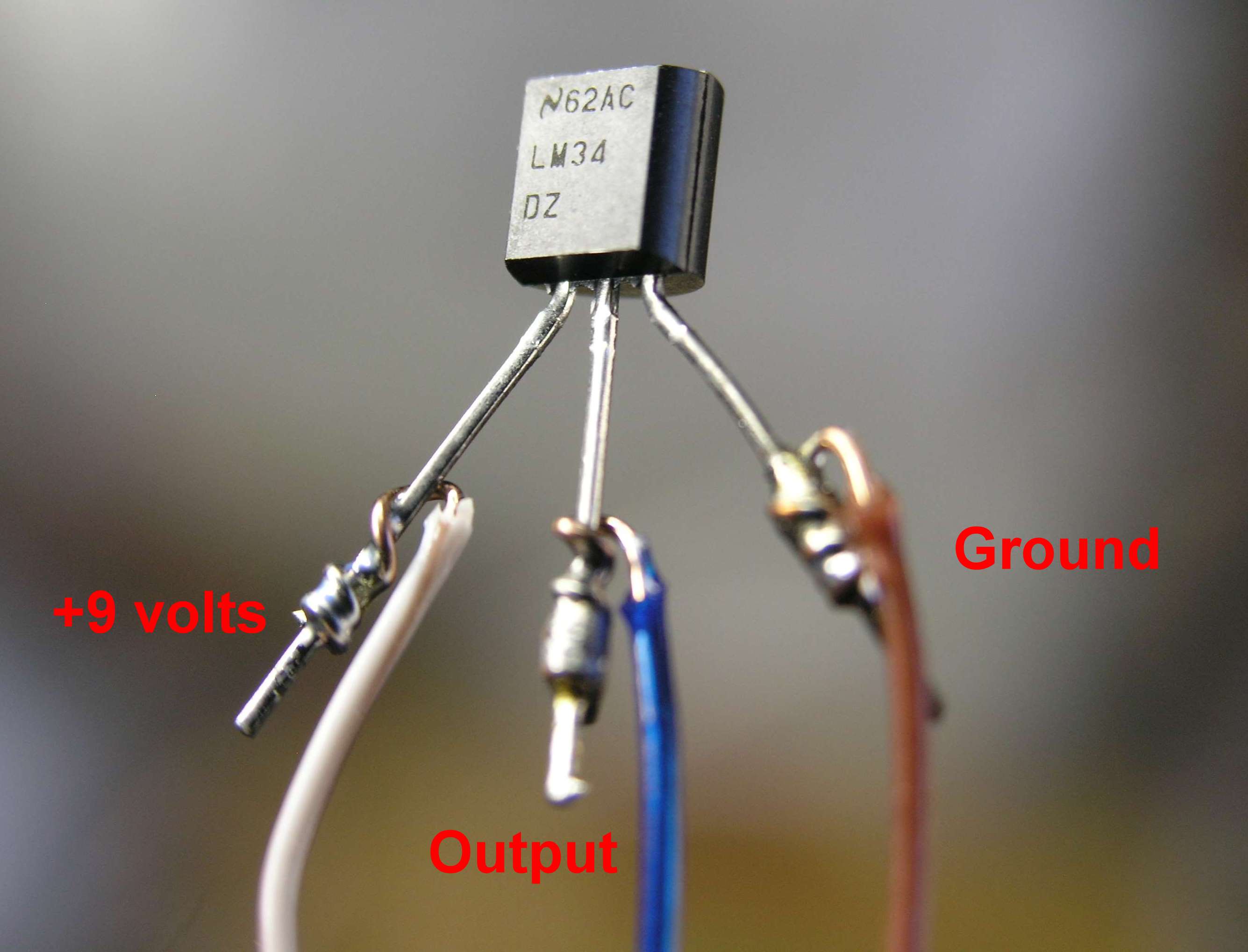
Experiment 9 : LM35 Temperature Sensor
An experiment to understand the working of an LM35 Temperature Sensor. LM35 is a common and easy-to-use temperature sensor. LM35 is a widely used temperature sensor with many different package types. At room temperature, it can achieve the accuracy of ±1/4°C without additional calibration processing. LM35 temperature sensor can produce different voltage by different temperature When temperature is 0 ℃, it outputs 0V; if increasing 1 ℃, the output voltage will increase 10 mv.
Components Required
- Arduino Uno Board*1
- LM35*1
- Breadboard*1
- Breadboard Jumper Wire*5
- USB cable*1
Circuit Diagrams
.png?raw=true)

Code
int potPin = 0; // initialize analog pin 0 for LM35 temperature sensor
void setup()
{
Serial.begin(9600);// set baud rate at”9600”
}
void loop()
{
int val;// define variable
int dat;// define variable
val=analogRead(0);// read the analog value of the sensor and assign it to val
dat=(125*val)>>8;// temperature calculation formula
Serial.print("Temperatuture");// output and display characters beginning with Tep
Serial.print(dat);// output and display value of dat
Serial.println("C");// display “C” characters
delay(2000);// wait for 2 second
}
Output
The temperature value is printed on serial monitor
Experiment 10:IR Remote Control Using TSOP
An experiment to understand the working of IR Remote Control using TSOP.
Components Required
- Arduino Uno Board*1
- Infrared Remote Controller(You can use TV Remote or any other remote) *1
- Infrared Receiver *1
- LED *6
- 220ΩResistor *6
- Breadboard Wire
- USB cable*1
Circuit Diagrams
.png?raw=true)
Code
#include <IRremote.h>
int RECV_PIN = 3;
int c=0;
IRrecv irrecv(RECV_PIN);
decode_results results;
void setup()
{
   pinMode(8, OUTPUT);
   pinMode(9, OUTPUT);
   pinMode(10, OUTPUT);
   pinMode(11, OUTPUT);
   pinMode(12, OUTPUT);

   Serial.begin(9600);
  irrecv.enableIRIn();
}
void loop() {
  if (irrecv.decode(&results)) {
    Serial.println(results.value);
    irrecv.resume();
  if(results.value==16773645)      //Up
  {
             digitalWrite(8,HIGH);
  }
  else if(results.value==4294967295)
  {
             digitalWrite(8,LOW);
  }
   if(results.value==16763445)  //Down
  {
             digitalWrite(9,HIGH);
  }
  else if(results.value==4294967295)
  {
             digitalWrite(9,LOW);
  }
    if(results.value==16769565) //left
  {
             digitalWrite(10,HIGH);
  }
  else if(results.value==4294967295)
  {
             digitalWrite(10,LOW);
  }
    if(results.value==16771605) //right
  {
             digitalWrite(11,HIGH);
  }
  else if(results.value==4294967295)
  {
             digitalWrite(11,LOW);
  }
    if(results.value==16714485) //ok
  {
             digitalWrite(12,HIGH);
  }
  else if(results.value==4294967295)
  {
             digitalWrite(12,LOW);
  }
  }
}
Output
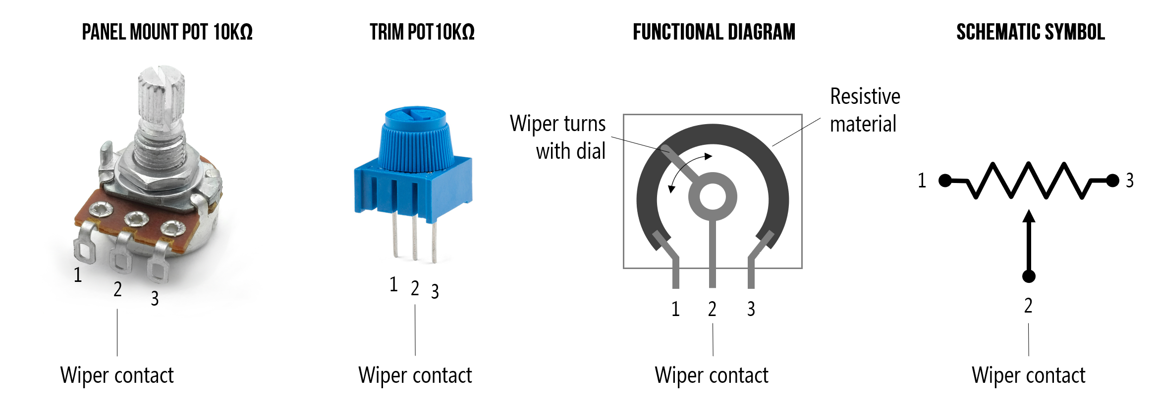
Experiment 11 :Potentiometer analog Value Reading
An experiment to understand the working of Potentiometer.
Components Required
- Arduino Uno Board*1
- 10K Potentiometer *1
- Breadboard*1
- Breadboard Jumper Wire*3
- USB cable*1
Circuit Diagrams
.png?raw=true)
Code
int potpin=0;// initialize analog pin 0
int ledpin=13;// initialize digital pin 13
int val=0;// define val, assign initial value 0
void setup()
{
pinMode(ledpin,OUTPUT);// set digital pin as “output”
Serial.begin(9600);// set baud rate at 9600
}
void loop()
{
digitalWrite(ledpin,HIGH);// turn on the LED on pin 13
delay(50);// wait for 0.05 second
digitalWrite(ledpin,LOW);// turn off the LED on pin 13
delay(50);// wait for 0.05 second
val=analogRead(potpin);// read the analog value of analog pin 0, and assign it to val
Serial.println(val);// display val’s value
}
Output
potentiometer values was showned in serial monitor.
Experiment 12 : 7 Segment Display
An experiment to understand the working of 7 Segment Display.
Components Required
- Arduino Uno Board*1
- digit LED Segment Display*1
- 220Ω Resistor*8
- Breadboard*1
- Breadboard Jumper Wires *several
- USB cable*1
Circuit Diagrams
.png?raw=true)
Code
int a=7;// set digital pin 7 for segment a
int b=6;// set digital pin 6 for segment b
int c=5;// set digital pin 5 for segment c
int d=10;// set digital pin 10 for segment d
int e=11;// set digital pin 11 for segment e
int f=8;// set digital pin 8 for segment f
int g=9;// set digital pin 9 for segment g
int dp=4;// set digital pin 4 for segment dp
void digital_0(void) // display number 5
{
unsigned char j;
digitalWrite(a,HIGH);
digitalWrite(b,HIGH);
digitalWrite(c,HIGH);
digitalWrite(d,HIGH);
digitalWrite(e,HIGH);
digitalWrite(f,HIGH);
digitalWrite(g,LOW);
digitalWrite(dp,LOW);
}
void digital_1(void) // display number 1
{
unsigned char j;
digitalWrite(c,HIGH);// set level as “high” for pin 5, turn on segment c
digitalWrite(b,HIGH);// turn on segment b
for(j=7;j<=11;j++)// turn off other segments
digitalWrite(j,LOW);
digitalWrite(dp,LOW);// turn off segment dp
}
void digital_2(void) // display number 2
{
unsigned char j;
digitalWrite(b,HIGH);
digitalWrite(a,HIGH);
for(j=9;j<=11;j++)
digitalWrite(j,HIGH);
digitalWrite(dp,LOW);
digitalWrite(c,LOW);
digitalWrite(f,LOW);
}
void digital_3(void) // display number 3
{digitalWrite(g,HIGH);
digitalWrite(a,HIGH);
digitalWrite(b,HIGH);
digitalWrite(c,HIGH);
digitalWrite(d,HIGH);
digitalWrite(dp,LOW);
digitalWrite(f,LOW);
digitalWrite(e,LOW);
}
void digital_4(void) // display number 4
{digitalWrite(c,HIGH);
digitalWrite(b,HIGH);
digitalWrite(f,HIGH);
digitalWrite(g,HIGH);
digitalWrite(dp,LOW);
digitalWrite(a,LOW);
digitalWrite(e,LOW);
digitalWrite(d,LOW);
}
void digital_5(void) // display number 5
{
unsigned char j;
digitalWrite(a,HIGH);
digitalWrite(b, LOW);
digitalWrite(c,HIGH);
digitalWrite(d,HIGH);
digitalWrite(e, LOW);
digitalWrite(f,HIGH);
digitalWrite(g,HIGH);
digitalWrite(dp,LOW);
}
void digital_6(void) // display number 6
{
unsigned char j;
for(j=7;j<=11;j++)
digitalWrite(j,HIGH);
digitalWrite(c,HIGH);
digitalWrite(dp,LOW);
digitalWrite(b,LOW);
}
void digital_7(void) // display number 7
{
unsigned char j;
for(j=5;j<=7;j++)
digitalWrite(j,HIGH);
digitalWrite(dp,LOW);
for(j=8;j<=11;j++)
digitalWrite(j,LOW);
}
void digital_8(void) // display number 8
{
unsigned char j;
for(j=5;j<=11;j++)
digitalWrite(j,HIGH);
digitalWrite(dp,LOW);
}
void digital_9(void) // display number 5
{
unsigned char j;
digitalWrite(a,HIGH);
digitalWrite(b,HIGH);
digitalWrite(c,HIGH);
digitalWrite(d,HIGH);
digitalWrite(e, LOW);
digitalWrite(f,HIGH);
digitalWrite(g,HIGH);
digitalWrite(dp,LOW);
}
void setup()
{
int i;// set variable
for(i=4;i<=11;i++)
pinMode(i,OUTPUT);// set pin 4-11as “output”
}
void loop()
{
while(1)
{
digital_0();// display number 0
delay(1000);// wait for 1s
digital_1();// display number 1
delay(1000);// wait for 1s
digital_2();// display number 2
delay(1000); // wait for 1s
digital_3();// display number 3
delay(1000); // wait for 1s
digital_4();// display number 4
delay(1000); // wait for 1s
digital_5();// display number 5
delay(1000); // wait for 1s
digital_6();// display number 6
delay(1000); // wait for 1s
digital_7();// display number 7
delay(1000); // wait for 1s
digital_8();// display number 8
delay(1000); // wait for 1s
digital_9();// display number 9
delay(1000); // wait for 1s
}
}
Output
Numbers displayed on the segement display
Assignment 1 : Automatic Night Light
An experiment to create automatic night lamp model using LDR and LED.
Components Required
- Arduino Uno Board
- Photo Resistor*1
- Yellow M5 LED*1
- 10KΩ Resistor*1
- 220Ω Resistor*1
- Breadboard*1
- Breadboard Jumper Wire
- USB cable*1
Circuit Diagrams
.png?raw=true)
const int ledPin = 13;
const int ldrPin = A0;
void setup() {
  Serial.begin(9600);
  pinMode(ledPin, OUTPUT);
  pinMode(ldrPin, INPUT);
}
void loop() {
  int ldrStatus = analogRead(ldrPin);
   if (ldrStatus <=300) {
    digitalWrite(ledPin, HIGH);
    Serial.println("LED is ON");
   }
  else {
    digitalWrite(ledPin, LOW);
    Serial.println("LED is OFF");
  }
}
Output
LED turnned on automatically, when its dark.
Assignment 2 : Digital Dice
An experiment to create a Digital Dice using 6 LEDs and 1 Push Button
Components Required
- Arduino Uno Board*1
- Breadboard*1
- Breadboard Jumper Wire
- USB cable*1
- LED*6
- Push Button*1
- 1KΩ Resistor*1
- 220Ω Resistor*6
Circuit Diagrams
.png?raw=true)
Code
#define DEBUG 0
// 6 consecutive digital pins for the LEDs
int first = 2;
int second = 3;
int third = 4;
int fourth = 5;
int fifth = 6;
int sixth = 7;
// pin for the button switch
int button = 12;
// value to check state of button switch
int pressed = 0;
void setup() {
  // set all LED pins to OUTPUT
  for (int i=first; i<=sixth; i++) {
    pinMode(i, OUTPUT);
  }
  // set buttin pin to INPUT
  pinMode(button, INPUT);

  // initialize random seed by noise from analog pin 0 (should be unconnected)
  randomSeed(analogRead(0));
  // if we're debugging, connect to serial
  #ifdef DEBUG
    Serial.begin(9600);
  #endif
}
void buildUpTension() {
  // light LEDs from left to right and back to build up tension
  // while waiting for the dice to be thrown
  // left to right
  for (int i=first; i<=sixth; i++) {
    if (i!=first) {
      digitalWrite(i-1, LOW);
    }
    digitalWrite(i, HIGH);
    delay(100);
  }
  // right to left
  for (int i=sixth; i>=first; i--) {
    if (i!=sixth) {
      digitalWrite(i+1, LOW);
    }
    digitalWrite(i, HIGH);
    delay(100);
  }
}

void showNumber(int number) {
  digitalWrite(first, HIGH);
  if (number >= 2) {
    digitalWrite(second, HIGH);
  }
  if (number >= 3) {
    digitalWrite(third, HIGH);
  }
  if (number >= 4) {
    digitalWrite(fourth, HIGH);
  }
  if (number >= 5) {
    digitalWrite(fifth, HIGH);
  }
  if (number == 6) {
    digitalWrite(sixth, HIGH);
  }
}
int throwDice() {
  // get a random number in the range [1,6]
  int randNumber = random(1,7);

  #ifdef DEBUG
    Serial.println(randNumber);
  #endif

  return randNumber;
}

void setAllLEDs(int value) {
  for (int i=first; i<=sixth; i++) {
    digitalWrite(i, value);
  }
}
void loop() {
  // if button is pressed - throw the dice
  pressed = digitalRead(button);

  if (pressed == HIGH) {
    // remove previous number
    setAllLEDs(LOW);
    buildUpTension();
    int thrownNumber = throwDice();
    showNumber(thrownNumber);
  }
}
Output
LEDs worked as a dice. different number of LEDs turned ON, When the button pressed each time.